Monthly Archives: August 2010

Introduction to MEF Programming

In the previous blog post, we discussed the MEF Architecture in detail. Let us start writing some code using MEF in C#.net. First things first, you need the current version of .NET Framework 4.0 and visual Studio 2010 to write code.

Note: For the UML diagrams, i am using the diagrams provided in the Architecture menu of Visual Studio 2010 Ultimate Edition. VS 2010 is not as powerful as Rational Rose or Enterprise Architect but you can design the basic UML diagrams.

Composition Basics:

Compose means To put things together to form a whole. Composition is used for objects that have a has-a relationship to each other. For ex, A car has-an engine, and has-a transmission, etc. A personal computer has-a CPU, has-a motherboard, etc.. we have designed classes that are composed of member variables which are built-in data types (eg. int, double, string, etc). Well, this is also an example of composition.

For ex, in C++, imagine we have the following two classes.

  1. class Class1
  2. {
  3.     ……….
  4.     ……….
  5. }


  1. class Class2
  2. {
  3.     public:
  4.             Class1 mobjclass1;        
  5.     ……….
  6.     ……….
  7. }


image   Fig: Composition relationship between class1 and class2. Class2 has a object of Class1.

The black diamond represents composition. It is placed on the Class2 class because it is the Class2 that is composed of a Class1. The arrowhead on the other end of the relationship denotes that the relationship is navigable in only one direction. That is, Class1 does not know about Class2. Composition is great but the disadvantage is that we introduce tight coupling (line 4 in Class2) resulting in higher code maintenance cost and difficult to extend the class for additional functionality.

prologue to MEF:

Ok, Let’s start with the most simple example: Hello World!!!

image Fig: Relationship diagram between the two classes

Let us assume a class SimpleGreetingClass, which has a member function public string SayHelloWorld(), which returns "Hello World !!!" string. Let us assume another class Program, which has an attribute SimpleGreetingClass mobjsimplegreetingclass.  Ones we create the object mobjsimplegreetingclass, we can call the member function SayHelloWorld() using this object. Following is the code for the same.

namespace MEFLab1
{
    public class SimpleGreetingClass
    {
        public string SayHelloWorld()
        {
            return "Hello World !!!";
        }
    }

    class Program
    {
        static void Main(string[] args)
        {
            Program program = new Program();
            program.Run();
        }

        void Run()
        {
            SimpleGreetingClass mobjsimplegreetingclass = new SimpleGreetingClass();
            Console.WriteLine(mobjsimplegreetingclass.SayHelloWorld());
            Console.ReadKey();
   
        }
    }
}


As we can see, there is a tight coupling between the SimpleGreetingClass and Program class. Also, the Program class must be aware of SimpleGreetingClass during the compilation time. Well, there are many disadvantages in this kind of design.

One of the USP (Unique Selling Point) of MEF is to solve this kind of tight coupling problem. Let us dive deep into MEF Programming and see how MEF solves this issue and other problems in the software world.

Enter the world of MEF:

The ABC’s of MEF are

  • Export it.
  • Import it.
  • Compose it.

Well, I am going to use some design pattern techniques  along with MEF as I always promote the best practices of software design in my architecture. Please observe the changes in the class diagram from the previous example. I used the IGreeting interface as it is a good practice to expose your contracts through interface (Facade Design Pattern). Our SimpleGreetingClass inherits IGreeting interface. This is the technique for Decoupling Implementation using an Interface. With out this, a tightly coupled relationship will be  formed between participating classes. This limits extensibility options as well as testability of the class itself. MEF allows imports to be decoupled from the exporter’s implementation by using an interface as the contract.

image  Fig: UML Class Diagram of the participating classes.

The source code can be downloaded from Google or Microsoft at  http://code.google.com/p/mef-dotnet/downloads/detail?name=MEFLab1.zip or from the link http://cid-38ecce05b21b8b44.office.live.com/self.aspx/MY%20Projects/MEFLab1.zip. Below is the detailed explanation of each of the projects present in solution1 in the attached zip file.

Coding the Interface Library :

  1. Create New Solution using VS 2010.
  2. Add a New Project –> Visual C# –> Class Library.Enter Name as  ContractsLibrary. Click OK. Add the following code.
  3. Here we are just creating an interface IGreeting so that the host application that can accept components through the IGreeting interface.
using System;
using System.Collections.Generic;
using System.Linq;
using System.Text;

namespace ContractsLibrary
{
    public interface IGreeting
    {
        string SayHelloWorld();
    }
}


Coding the MEFPart1 Library:

  1. Add a New Project –> Visual C# –> Class Library.Enter Name as  MEFPart1. Click OK. Add the following code.
  2. Add a reference to the System.ComponentModel.Composition assembly.
  3. Add a reference to the ContractsLibrary.DLL assembly.
  4. Add the following using statement:
    • using System.ComponentModel.Composition; This allows us to specify the attributes for using MEF.
    • using ContractsLibrary;
  5. Add the following code.
using System.ComponentModel.Composition;
using ContractsLibrary;

namespace MEFPart1
{
    [Export(typeof(IGreeting))]
    public class SimpleGreetingClass : IGreeting
    {
        public string SayHelloWorld()
        {
            return "Hello World !!!";
        }
    }
}

Here, MEF makes this piece of code available to other components as it is specified(decorated) with attribute [Export]. We know that the contract consists of a string, called the contract name, and the type of the exported or imported object, called the contract type. Only if both the contract name and contract type match is an export considered to fulfill a particular import. Let us examine the line [Export(typeof(IGreeting))] ; the contract type is IGreeting because it is specified as a parameter of the Export attribute. The exported type must be either the same as the contract type, derive from the contract type, or implement the contract type if it is an interface. In this export, the actual type SimpleGreetingClass implements the interface IGreeting.

So in this case, the contract type will be IGreeting, and the contract name will be a unique string created from the contract type. In other words, the contract name will match only exports whose names are also inferred from the type IGreeting.

Coding the MainExe:

  1. Add a New Project –> Visual C# –> Console Application.Enter Name as  MainExe. Click OK. Add the following code.
  2. Add a reference to the System.ComponentModel.Composition assembly.
  3. Add a reference to the ContractsLibrary.DLL assembly.
  4. Add the following using statement:
    • using System.ComponentModel.Composition; This allows us to specify the attributes for using MEF.
    • using System.ComponentModel.Composition.Hosting;
    • using ContractsLibrary;
  5. Add the following code.
using System;
using System.IO;
using System.Reflection;
using System.ComponentModel.Composition;
using System.ComponentModel.Composition.Hosting;
//using System.ComponentModel.Composition.Primitives;
using ContractsLibrary;
using System.Collections.Generic;


namespace meflab1
{
    class Program
    {
        [Import(typeof(IGreeting))]
        public IGreeting Greetings { get; set; }

        static void Main(string[] args)
        {
            Program program = new Program();
            program.Run();
        }

        public Program()
        {
            try
            {
                AggregateCatalog aggregatecatalogue = new AggregateCatalog();
                //aggregatecatalogue.Catalogs.Add(new AssemblyCatalog(Assembly.GetExecutingAssembly()));
                aggregatecatalogue.Catalogs.Add(new DirectoryCatalog(AppDomain.CurrentDomain.BaseDirectory));

                CompositionContainer container = new CompositionContainer(aggregatecatalogue);
                container.ComposeParts(this);
    
            }
            catch (FileNotFoundException fnfex)
            {
                Console.WriteLine(fnfex.Message);
            }
            catch (CompositionException cex)
            {
                Console.WriteLine(cex.Message);
            }
        }

        void Run()
        {
            if (Greetings != null)
            {
                Console.WriteLine(Greetings.SayHelloWorld());
                Console.ReadKey();
            }
        }
    }
}

Observe the code

[Import]

public IGreeting Greetings { get; set; }

The [Import] attribute declares something to be an import; that is, it will be filled by the composition engine when the object is composed. Every import has a contract, which determines what exports it will be matched with. The contract can be an explicitly specified string, or it can be automatically generated by MEF from a given type, in this case the interface IGreeting. Any export declared with a matching contract will fulfill this import. In this import, the Import attribute has neither a contract type nor a contract name parameter attached. Therefore, both will be inferred from the decorated property. In this case, the contract type will be IGreeting, and the contract name will be a unique string created from the contract type. MEF will automatically assume the contract to be based on the type of the import unless you specify it explicitly. We can also code it as [Import(typeof(IGreeting))].

MEF Composition explained:

With MEFPart1 and ContractsLibrary in place, you can now start composition. MEF parts don’t automatically get discovered or created. Instead, you need to write some bootstrapping code that will enact composition. A common place to do this is in our application’s entry point, which in this case is the Program class.

To bootstrap MEF involves a few steps:

  • Add imports of the contracts you need the container to create, which i explained in the above section.
  • Create a catalog that MEF uses to discover parts.
  • Create a container that composes instances of parts.
  • Compose by calling the Composeparts method on the container and passing in the instance that has the imports.

As you can see here, I added a IGreeting import on the Program class. Then I created a DirectoryCatalog pointing to the base folder containing the MainExe. Then created a container that uses the catalog. Finally, I called Composeparts, which caused an App instance to be composed and the IGreeting import to be satisfied.

During composition, the container will create the IGreeting and satisfy its SimpleGreetingClass import. This will result in SimpleGreetingClass being created. Finally, the Application class will have its IGreeting import satisfied. In this way, MEF has assembled the entire object graph based on declarative information, rather than manually requiring imperative code to do the assembly. As i said before, container acts as a match maker.

Epilogue:

Build the solution and run the Mainexe. The console window pops up and displays the following error information.

The composition remains unchanged. The changes were rejected because of the following error(s): The composition produced a single composition error. The root cause is provided below. Review the CompositionException.Errors property for more detailed information.

1) No valid exports were found that match the constraint ‘((exportDefinition.ContractName == "ContractsLibrary.IGreeting") AndAlso (exportDefinition.Metadata.ContainsKey("ExportTypeIdentity") AndAlso "ContractsLibrary.IGreeting".Equals(exportDefinition.Metadata.get_Item("ExportTypeIdentity"))))’, invalid exports may have been rejected.

Resulting in: Cannot set import ‘meflab1.Program.Greetings (ContractName="ContractsLibrary.IGreeting")’ on part ‘meflab1.Program’. Element: meflab1.Program.Greetings (ContractName="ContractsLibrary.IGreeting") –

->  meflab1.Program

Press any key to continue . . .

The reason is that the [Import] in the MainExe could not be satisfied as there the catalog provided to the container does not have any parts.

Copy the MEFPart1.DLL to the folder containing the MainExe executable. Then run the MainExe and you can see Hello World!!! on the console window. This is because we used directory catalog and it detects all the parts present in the directory and provides it to the container to satisfy the exports and import definitions.

I will be explaining other concepts of MEF in my upcoming blog. Below is the Class Diagram and Sequence Diagram for the code that i am writing.

image

image 

“A leader takes people where they want to go. A great leader takes people where they don’t necessarily want to go, but ought to be.”

Download Source Code from: http://cid-38ecce05b21b8b44.office.live.com/self.aspx/MY%20Projects/MEFLab1.zip

MEF Architecture in Detail

Let us take a deep dive into the MEF architecture. We can write sample applications by just going through the MEF knowledge base on the web. But to design an enterprise level of applications, it requires more in depth knowledge of what MEF is trying to solve, what MEF is, where it can be applied and how MEF is architected and designed to solve the existing issues in the software world.

Well, i did not invent MEF, so some of the information present in the blog is from the web. According to me, MEF is an Extensible Framework for composing applications from a set of loosely-coupled parts discovered and evolving at run-time. It is basically a composition framework.

What does MEF solve?

  • Managed Extensibility Framework is to solve the old problem of maintaining a piece of statically compiled software that continuously changes and evolves during its lifetime. MEF provides a solution for building reusable applications from reusable components which can be dynamically discovered at runtime by the application itself.
  • MEF offers a solution for extending the application architecture as it evolves.
  • With MEF, we can add additional metadata to the piece of code we write thus facilitating rich querying and filtering.
  • MEF is not a Dependency Injection container. DI is only a part of the solution that MEF tries to bring into the scene.

Why MEF?

From the efforts point of view, we approximately spend 20% to develop the original application and about 80% to maintain it during the years. If we could turn at least a part of that paining 80% to something more useful—for example inventing into creating better business value or user experience, etc.—both the customers and the company would be happier. That is where MEF comes into the picture from business perspective.

MEF Architecture

arch1

Fig: Different layers in the Managed Extensions Framework.

Container:

The namespaces of the different containers are as follows:

System.ComponentModel.Composition.Hosting.AggregateExportProvider
System.ComponentModel.Composition.Hosting.CatalogExportProvider
System.ComponentModel.Composition.Hosting.ComposablePartExportProvider
System.ComponentModel.Composition.Hosting.CompositionContainer

image     Fig: Class Hierarchy of the Containers.

The Container layer provides the public API’s to the users to use MEF. Let us examine the container layer.

CompositionContainer – The composition container, “CompositionContainer”, is present in the namespace System.ComponentModel.Composition.Hosting. The container contains a collection of parts that were either created by the container or added to it by the application. Parts contain a collection of exports (services it offers including itself) and imports (services it consumes) with imports being optional or required. One a Part has been added to the container, it can be composed. During composition, the container satisfies all of a Part’s imports based on available exports. If a required import cannot be satisfied, then composition will fail.

A CompositionContainer object serves two major purposes in an application. First, it keeps track of which parts are available for composition and what their dependencies are, and serves as the context for any given composition. Second, it provides the methods by which the application can initiate composition, get instances of composed parts, or fill the dependencies of a composable part. Parts can be made available to the container either directly or through the Catalog property. All the parts discoverable in this ComposablePartCatalog are available to the container to fulfill imports, along with any parts added directly.

ComposablePartExportProvider – This provider is responsible for retrieving exports from part catalogs. It contains a collection of parts. However the parts in it’s collection are created from the PartDefinitions it queries rather than being explicitly added to it. Also it contains a CompositionEngine for satisfying the imports on it’s parts.

CatalogExportProvider – Retrieves exports from a catalog.

AggregatingExportProvider – This provider is a composite of other providers that it contains, and is used for providing a topology of EPs. Whenever this provider is queried, it will query the providers within. The internal query behavior varies depending on the cardinality of the ImportDefinition that is passed in.  It queries it’s children. The container uses an AggregatingEP internally which contains a ComposablepartEP, a CatalogEP and/or a custom provider if one was passed in during its construction. AggregatingEPs can also be nested without a problem.

arch2.png

Fig: The chained set of ExportProvider instances in use by a container instance, so they can query each other for exports when satisfying dependencies.

Primitives:

Namespace: System.ComponentModel.Composition.Primitives

The Primitives is an abstraction layer. This layer provides a layer of indirection so MEF won’t be tight coupled with a single approach to part discovery, imports/exports definitions.  Actually, catalogs provide the available components to the container through this layer. The primitives provide APIs for describing, creating, and using components.

image

Fig: Overall view of the primitive classes.

The primitives represent component instances capable of being wired together, component definitions with rich meta data and common query interfaces for component catalogs. The role of the Primitives is to specify components that can be wired together to create useful software.

ComposablePart is an instance of live executing software component. The ComposablePart specifies its dependencies and capabilities through import and export respectively. The ComposablePart describes its own imports though ImportDefinition and exports through ExportDefinition

ExportDefinition is a structure comprising of a string-based ContractName and a dictionary of additional information called metadata. Each ExportDefnition attached to a composablepart describes the individual capability (service offered) of the part. Metadata is useful to perform some additional querying or filtering on the part.

ImportDefinition It describes the dependency of the part. IsRecomposable is useful to indicates whether the import definition can be satisfied multiple times. IsPrerequisite indicates whether the import definition must be satisfied  before a part can start producing exported objects.

ComposablePartDefinition describes the kinds of ComposablePart that can be created in a given system. It defines an abstract base class for composable part definitions, which describe and enable the creation of ComposablePart objects. CreatePart method creates a new instance of a part that the ComposablePartDefinition describes.

ComposablePartCatalog The ComposablePartDefinitions are grouped together into ComposablePartCatalogs. Using IQueryable<ComposablePartDefinition> Parts property, we can get the part definitions that are contained in the catalog.


Attributed Programming Model

Namespace: System.ComponentModel.Composition.Hosting

We can directly use the above mentioned Primitives in our applications to perform composition and other tasks but it is very laborious task. So there should be a way for the developers to interact with the primitives using some programming model. APM optimize the task of mapping a class or interface and members to a ComposablePartDefinition with exports and imports.

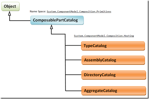
image   Fig: Class Hierarchy of different types of Catalogs

The Attributed Programming Model is the implementation of the primitive layer.  Different catalogs can provide components that are defined using different programming models.  The default programming model for MEF is the attributed programming model which uses the Import and Export attributes.  The TypeCatalog, AssemblyCatalog, and DirectoryCatalog that ship with MEF use this programming model. The ability to use a different programming model provides a lot of flexibility.  Instead of using the Import and Export attributes, you could have your imports and exports defined based on a convention or an external configuration file.  You could also write a catalog where the components are defined using a dynamic language such as IronPython or IronRuby.  And you can use an AggregateCatalog to combine all of these catalogs and use them all together in the same container.

The primary interfaces to the Attributed Programming Model are:

  • TypeCatalog : Catalog containing discovered types
  • AssemblyCatalog: Catalog containing parts that are discovered in an assembly.
  • DirectoryCatalog: Catalog containing parts that are discovered in the directory.
  • AggregareCatalog: It holds the collection of Catalogs.

Well, that’s the high level view of the MEF internal structure. As mentioned earlier, the developer can use this framework using any programming model. In .Net 4.0, Microsoft provided the Attributed Programming Model to the developers to code the applications using MEF. Primitives are an abstraction layer, so tomorrow you can move from APM to any other model easily.

Watch out for my upcoming blogs for some hands on coding…

Scrum Process for Software Development using Microsoft Visual Studio Scrum 1.0 Process Template

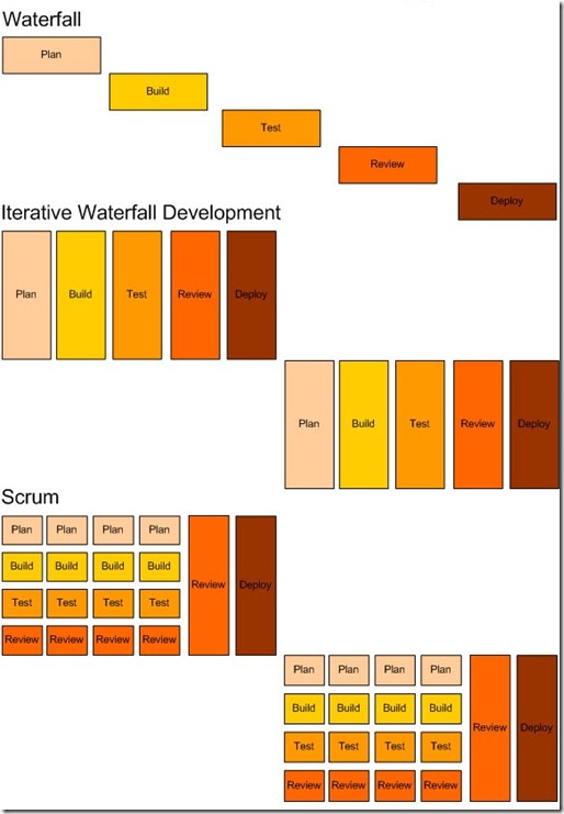
In the last 14 years, I had seen myself moving from waterfall methodology of software development to Iterative and then to Scrum and finally to Scrum-ban. I will explain a bit about the different methodologies and then move to Scrum Process. Below is the pictorial representation of the Waterfall, Iterative and Scrum software development process. More info about Kanban and Scrum-ban will be posted in my upcoming blogs. In this article, i would like to demo on how to use the Microsoft Visual Studio Scrum 1.0, process template built specifically for Scrum teams

the-difference-between-waterfall-iterative-waterfall-scrum

Picture 1: Pictorial representation of Waterfall, Iterative and Scrum Software Development methodologies.

The waterfall approach is highly risky, often more costly and generally less efficient than more Agile approaches. It requires the creation of up-front documentation before any real business value is created. i.e. You don’t realize any value until the end of the project. This is confounded by the fact that product development is started downstream, or much later in the project’s expected timeframe. This has the obvious disadvantage of delaying the point at which business value can be realized.

Remember the 80-20 rule, 80% of a product’s value comes from 20% of its features. With this in mind, can we conceivably build a software product that provides 20% of the feature set? Yes, We can deliver "version 1" with 20% of the features, then, a little later, "version 2" with a further collection of features and later "version 3". The beauty of this approach is that development of 20% of the features should not take 100% of the project’s expected schedule and budget: we can realize business value much earlier in the cycle.

Iterative Waterfall Development focuses on delivering a sprint of work as opposed to a series of valuable/shippable features. In my experience, The most commonly occurring issue in this type of process is you deliver loads of code and leave it until the last minute to test everything. One issue takes longer than expected to resolve, you miss your sprint deadline and you deliver nothing. Another common symptom of this type of approach is over-commitment.  It’s really difficult to estimate the total effort associated with a particular User Story/Feature when approaching delivery in this phased way.  You’re more or less forced to estimate each phase separately (e.g. estimate development separately to testing in this instance) – this doesn’t work as the phases are not separate, they’re totally intertwined. For example, if you find an issue with the test, you must return to development. The whole team must remain focused on delivering the end goal, not the separate phases. It’s also worth noting that velocity and burn downs are far less (if at all) useful in this type of environment – you don’t benefit from early-warning-signs as you don’t find out whether you’re on track until the end of the sprint.

Scrum Development focuses on delivering fully-tested, independent, valuable, small features. As such, we diversify our risk – if one feature goes wrong, it should not impact another feature. With that said, we still plan our work in iterations and we will still release at the end of each iteration.

For Example, if we run two projects for identical requirements, same time period (For ex: say 1 year) with same team, but one in waterfall Software development process and another in scrum. Assuming you know how scrum and waterfall both work, if you look at the project delivery after 6 months, it would be very interesting output. In the 6 months, the waterfall project might have reached a stage where the requirement analysis is fully complete, design is complete, programming has started and half way through. If I am a customer, how much business value this stage would give me, think about it? At the same time, the scrum project team would have against prioritized product backlog and started delivering shippable product after every sprint (say of 4 scrum cycles every 2 month). Scrum focuses on shippable product in small iterations, and that not only gives the best business value at certain moment in project life cycle but also allows change during the development process that can be taken up in future sprints.


Microsoft Visual Studio Scrum 1.0 Process Template

Last week, Microsoft announced Microsoft Visual Studio Scrum 1.0, a process template built from the ground up specifically for Scrum teams. Below is the step by step guide to Downloading, Installing and setting up the Scrum process for the Project Teams.

Step 1: Downloading the Microsoft Visual Studio Scrum 1.0 Process Template:

There are two ways to download the template.

Option 1: Download from the link Microsoft Visual Studio Scrum 1.0 from the Visual Studio Gallery

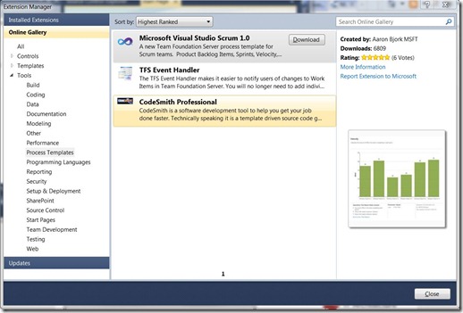
Option 2: Download Microsoft Visual Studio Scrum 1.0 using Visual Studio 2010 using the following steps.

  1. Open VS 2010

  2. On the Tools menu, click Extension Manager.

  3. In Extension Manager, in the left pane, click Online Gallery.

  4. In Online Gallery, click on Tools and select Process Templates

  5. In the right pane, Select Microsoft Visual Studio Scrum 1.0 and  click on the Download button.
  6. This will download the Microsoft_Visual_Studio_Scrum_1.0.MSI to the location you select in the download dialog.
  7. Click on the Microsoft_Visual_Studio_Scrum_1.0.MSI file to start the installation.
  8. The MSI installs the required files to the location (default) C:\Program Files (x86)\Microsoft\Microsoft Visual Studio Scrum 1.0. (I am running Windows 7, 64 bit OS)

Capture

Step 2: Launch the Process Template Explorer in Visual Studio 2010

If you already have a connection to the Team Foundation Server, please ignore the Steps A to D and go to Step 1.

Prerequisite: The following process requires a connection to a Team Foundation Server. In my scenario, i Installed Microsoft Team Foundation Server 2010 locally on Windows 7 PC. Below are the steps to connect to a Team Foundation Server (team project collection).

Step A. In Visual Studio, on the Tools menu, click Connect to Team Foundation Server.

image

Note
If you do not see this option, you have not installed Team Explorer. You must install Team Explorer before you will have the option to connect to Team Foundation Server.

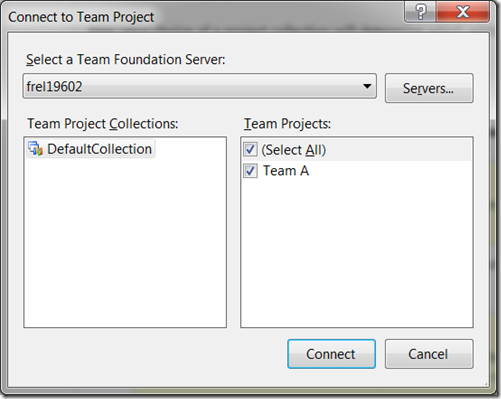
Step B. In the Connect to Team Project dialog box, in the Select a Team Foundation Server drop-down list, click the server that contains the team project collection to which you want to add your team project. image 

Note
If the drop-down list is empty, click the Servers button to manually enter the server connection settings. Contact your Team Foundation administrator or team project administrator to obtain the connection settings.
image

Step C. Click the name of the project collection to which you want to add your team project from the Directory list

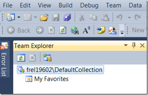
Step D. Click Connect. The Team Explorer displays the team projects that you selected. Following is the screenshot of my Team Projects.image

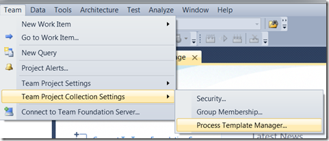
  1. In VS 2010, Click on Team menu
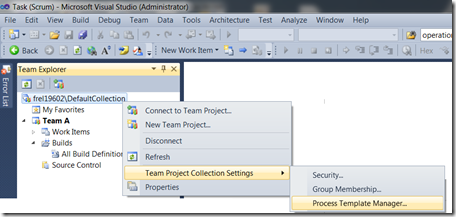
  2. Select Team Project Collection SettingsProcess Template Manager. image OR in Team Explorer window, right click on the collection, select Team Project Collection Settings Process Template Manager. image
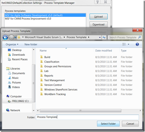
  3. Click Upload button and select the folder where the Microsoft Visual Studio Scrum 1.0 process template is installed (Default: C:\Program Files (x86)\Microsoft\Microsoft Visual Studio Scrum 1.0\Process Template). Click on Select Folder button.image image
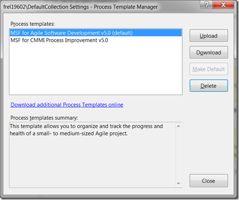
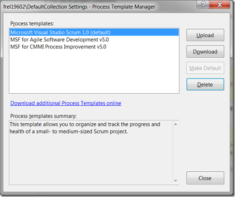
  4. Once installed, Click on Make Default button to make it the default process template. The Microsoft Visual Studio Scrum 1.0 should be listed in the Process Template Manager as follows:image

Create a Team Project

  1. In Team Explorer, right-click the project collection, and then click New Team Project. image OR   open the File menu, point to New, and then click Team Project.image
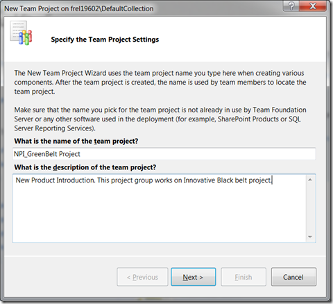
  2. On the Specify the Team Project Settings page, in the What is the name of the team project? box, type a name for the team project that you want to create and type the description of the project.image 

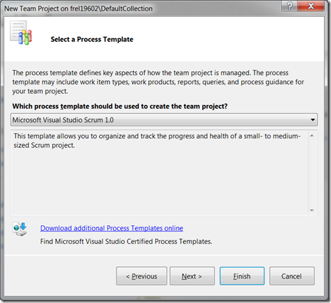
  3. Click Next. On the Select a Process Template page, in the Which process template should be used to create the team project? list, click on Microsoft Visual Studio Scrum 1.0 template. Click on Finishimage

The following tasks are performed automatically:

  • A SharePoint site for your team project is created.

  • An empty version-control folder for your team project is created.

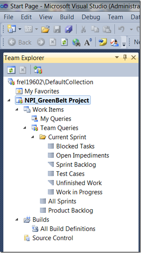
Team Explorer displays the following informationimage 

To start using the Scrum process, refer to the site http://msdn.microsoft.com/en-us/library/ff731587.aspx